Marbles Groupbuy
I organized a group buy of 30 partially assembled Mutable Instruments Marbles eurorack modules on the Sourcery Studios Discord in 2021! We ordered the PCBs with almost all SMT components already assembled at JLCPCB and bought the remaining components required for hand assembly. I handled all the logistics, from ordering the boards and components to shipping all the packages.
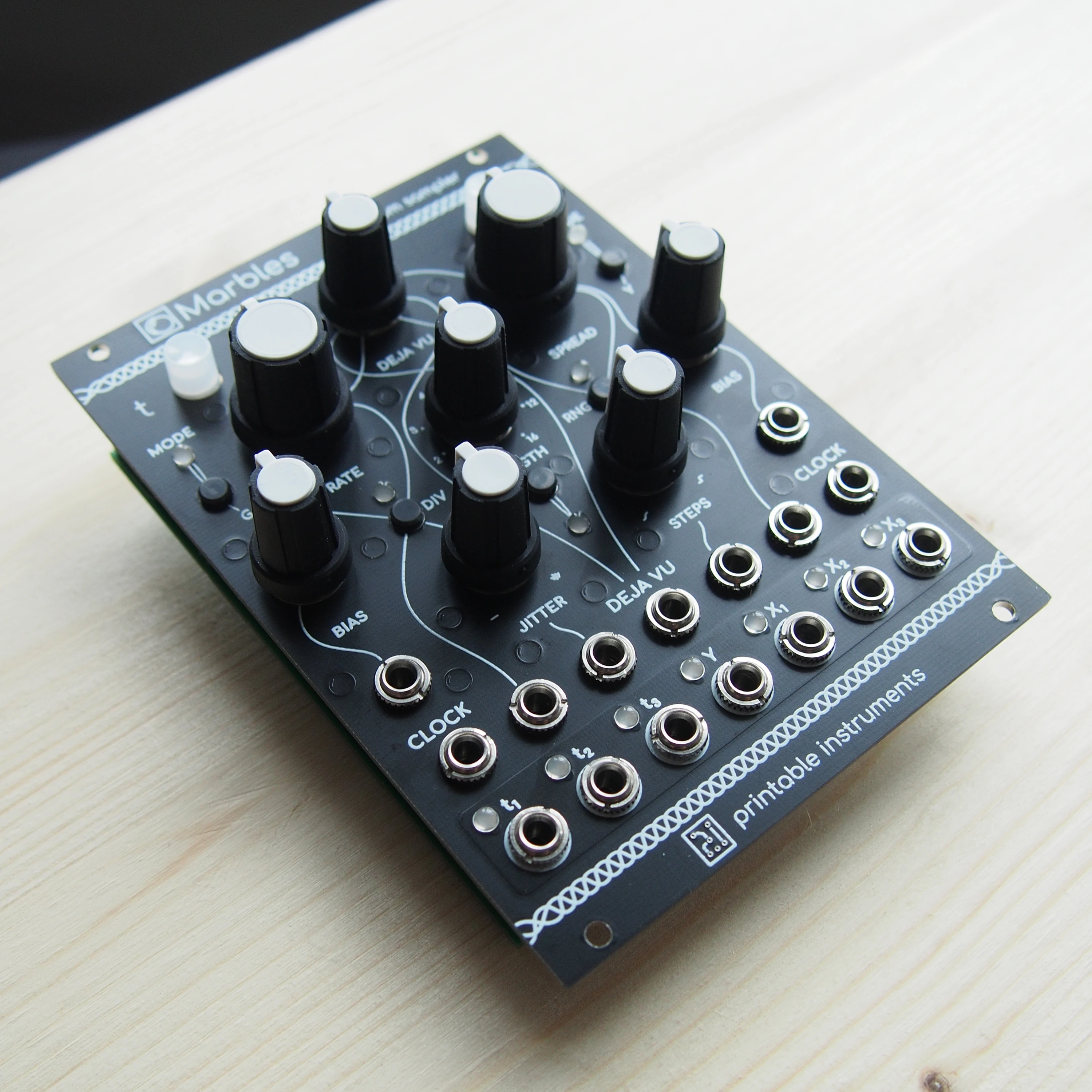
Here are some pictures of the finished module:

# Assembly Guide
I created the following guide to help with assembling the remaining surface mount components, through hole components, building and flashing the firmware, as well as calibrating the module.
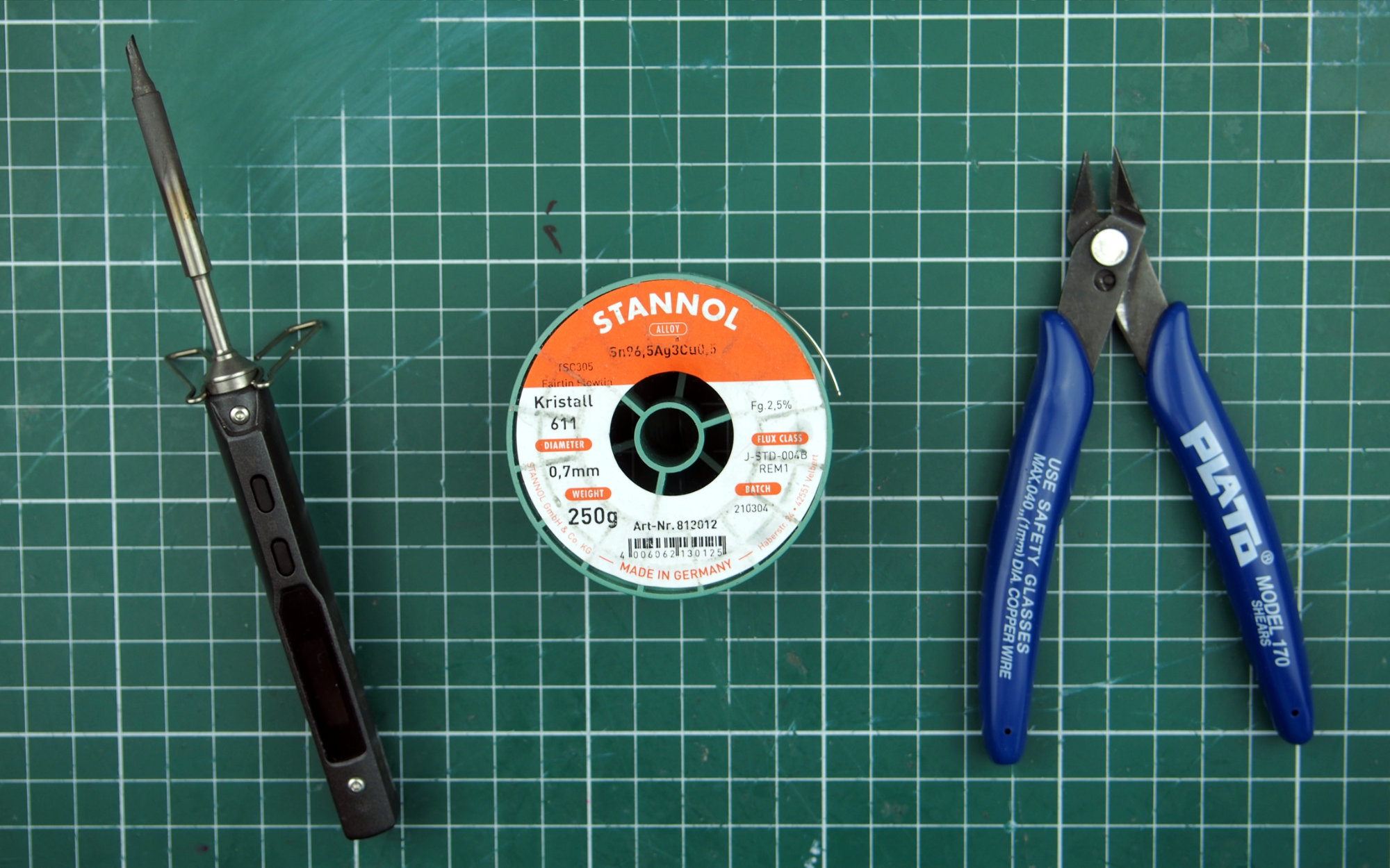
Required Tools:
- soldering iron (preferably with a big shovel tip)
- high quality lead-free solder (preferably <= 0.8mm)
- flush cutter
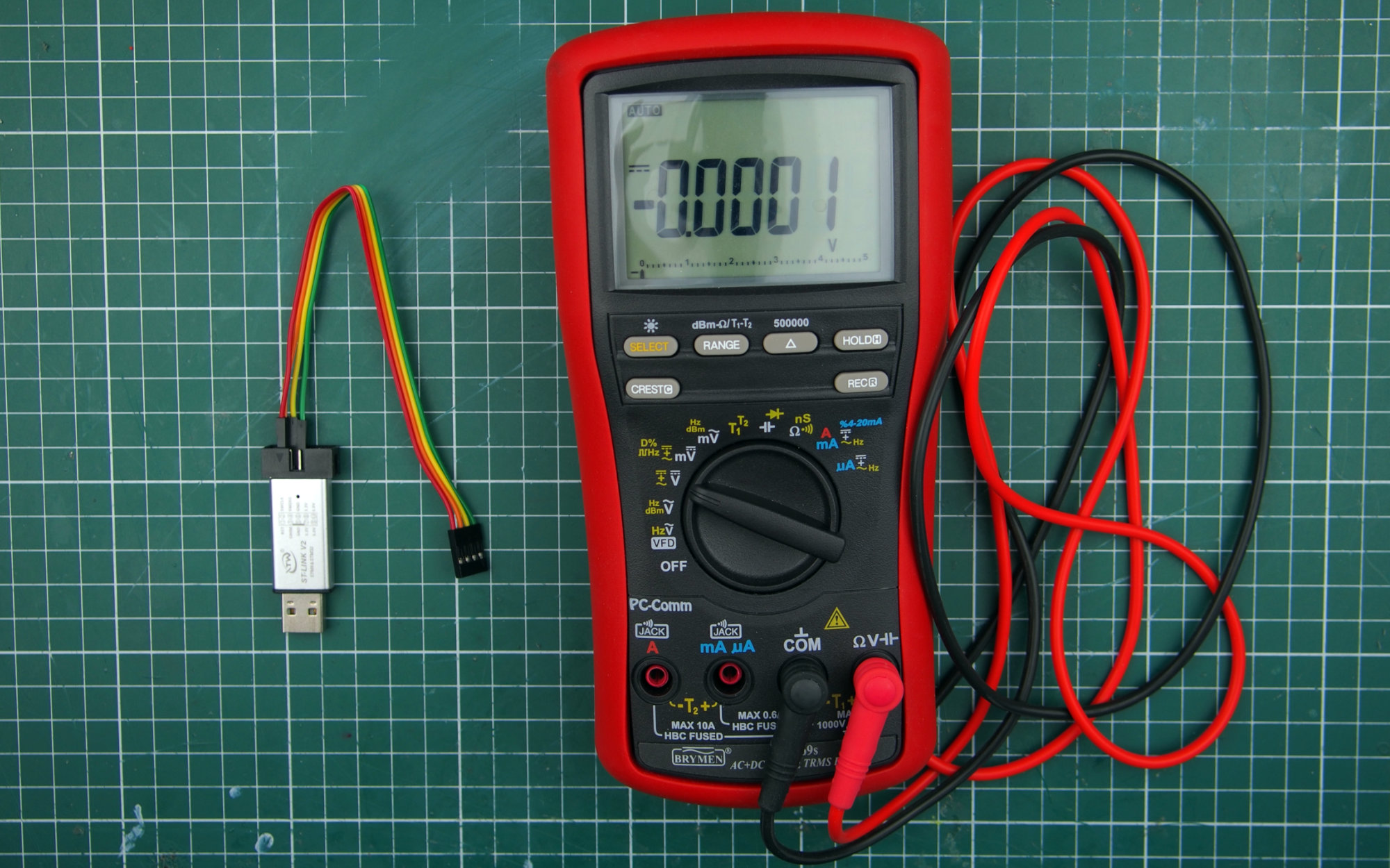
For Flashing/Calibration:
- ST-LINK programmer (i'm using a cheap ST-LINK/V2 clone)
- eurorack power supply
- digital multimeter (the more digits the better, i'm using a 5 4/5 digit one, ideally one would use a 6 1/2 digit one, but more inaccurate ones will also work fine, the calibration just won't be as precise)
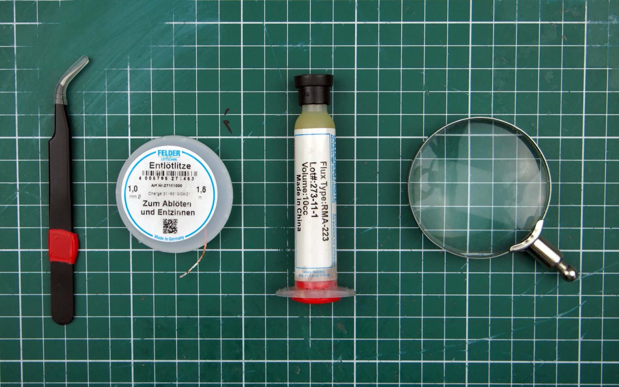
For SMT Assembly:
- tweezers
- solder wick (preferably <= 1mm)
- soldering flux
- magnifying glass
- hot air station (optional)
# SMT Assembly
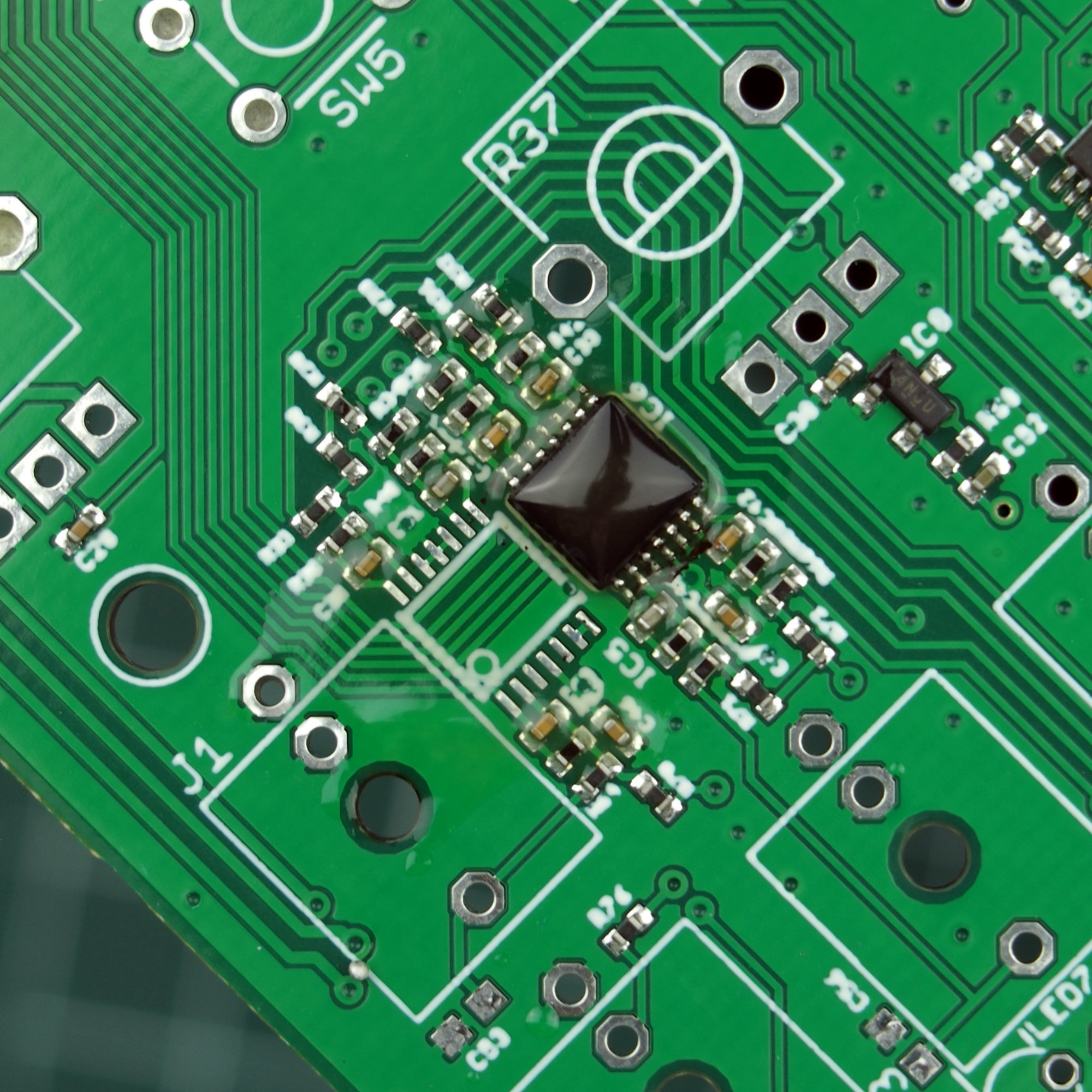
Soldering the two MCP6004s and the DAC8164
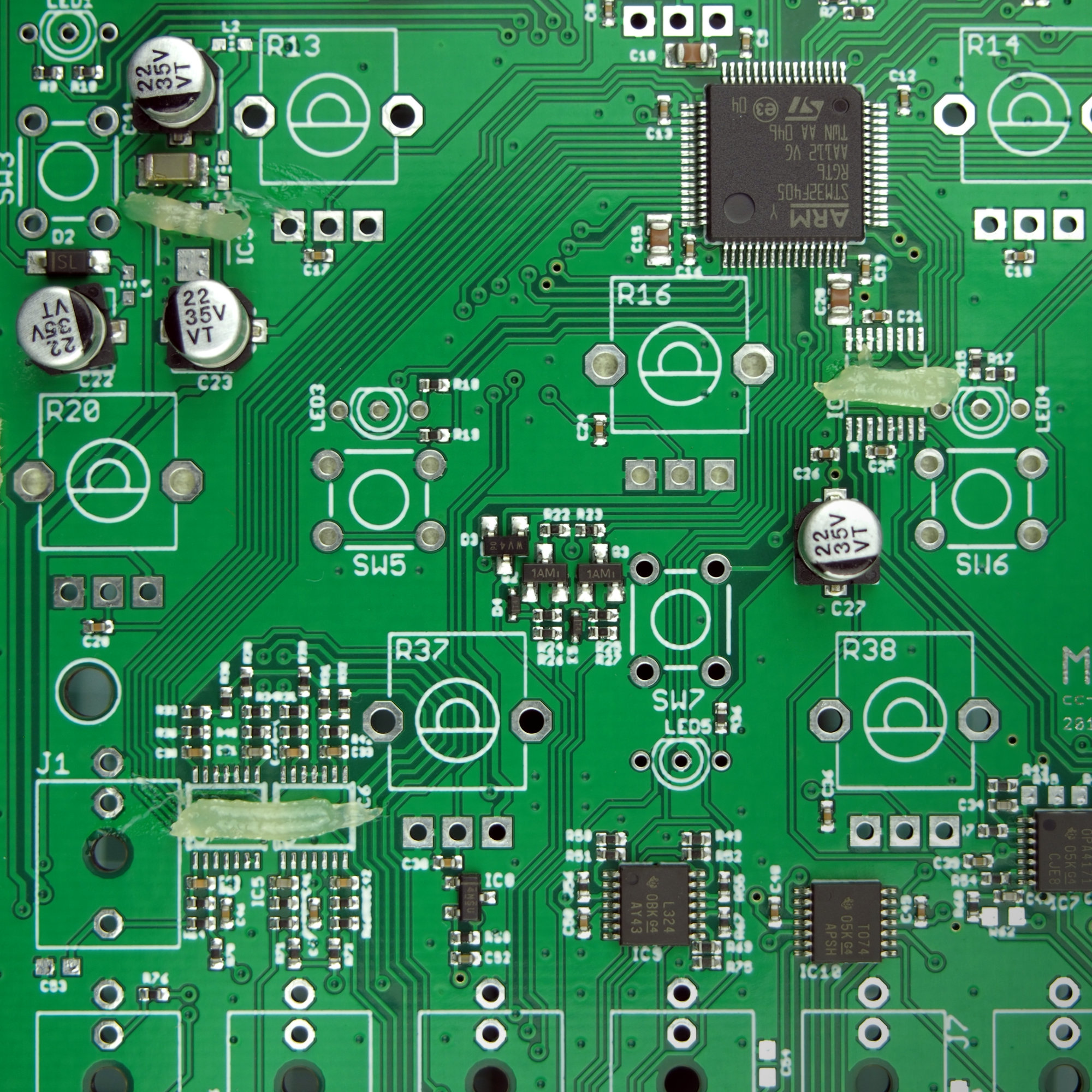
Apply some flux to the IC5, IC6, IC4 and IC3 footprints. This will help with keeping the ICs in place while soldering and also make the solder flow better. If using a "solid" (grease like) type of flux, heat it gently with your soldering iron to make it spread properly.
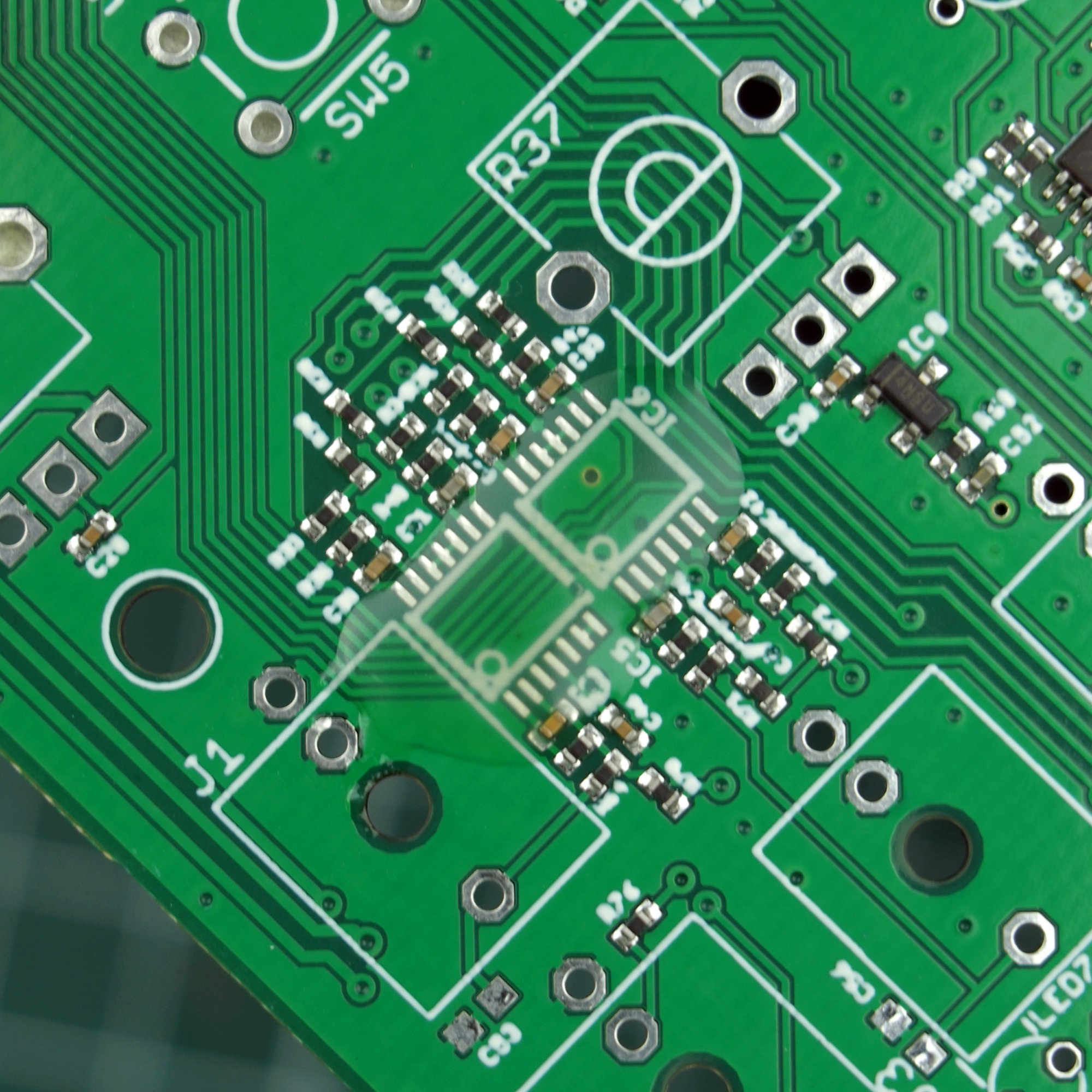
Next, place and press each IC carefully into the flux. Make sure the legs are well aligned. I like to reflow my flux again, so that it gets transparent, after that I check the alignment with a magnifying glass.
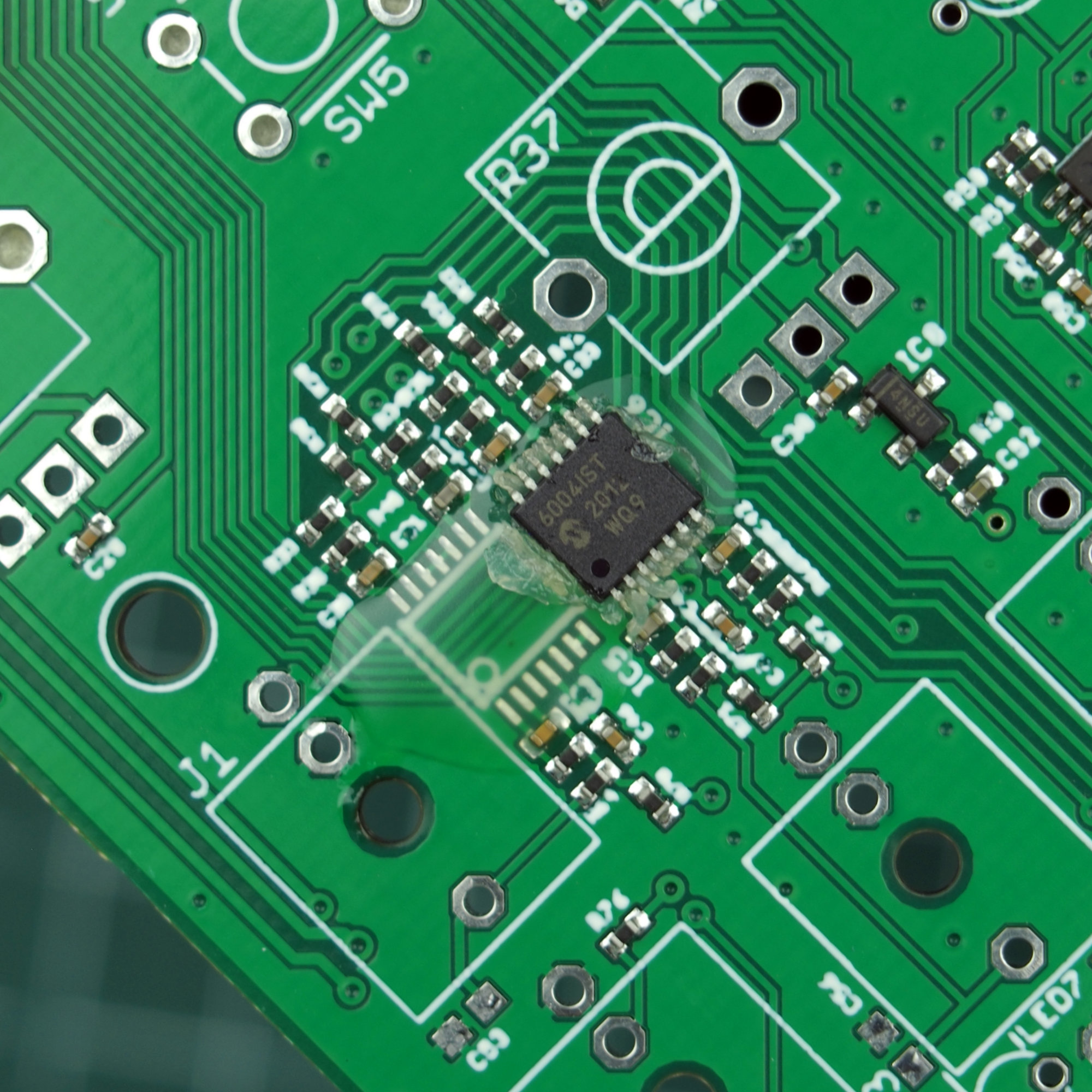
Get a little amount of solder onto your soldering iron and carefully solder a few pins to the board, to fix the IC in place. Make sure the solder is properly bonding to the pads, by lightly tapping the IC with some tweezers. Also make sure its still aligned properly, if it isn't, now is the best moment to try and realign it.
Solder all the pins on the opposite side from the one you fixed. You don't need to worry about shorts while doing that, but should rather make sure that every pin gets some solder. Repeat the same process on the other side.
Be careful when soldering the MCP6004s. There are lots of small 0402 components right next to the pins which are pretty easy to knock off if you aren't careful with the iron.
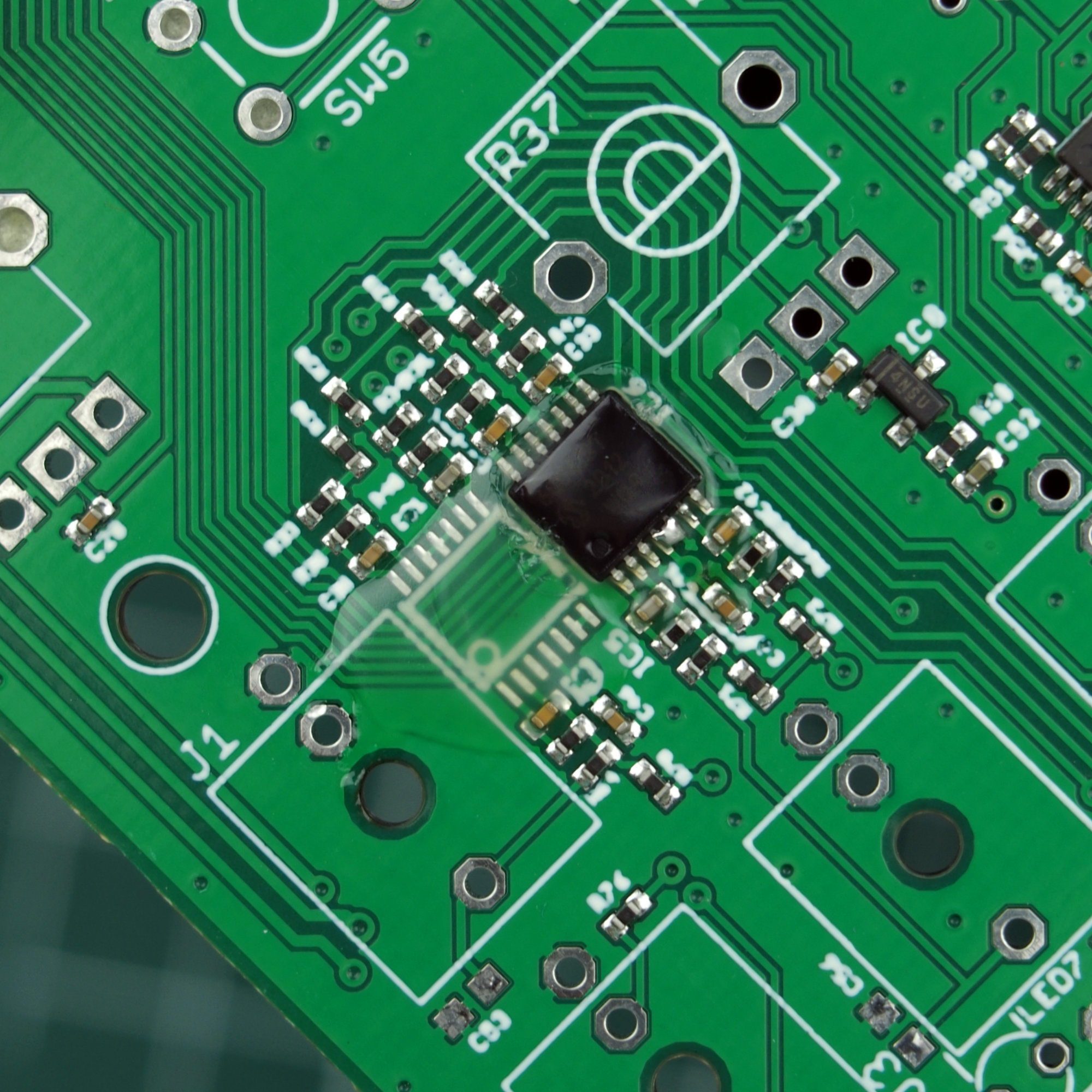
Then, carefully get rid of the remaining solder and any shorts with some solder wick. If it ever gets stuck on the pins, don't pull on it. Doing that could best case bend some pins and worst case, pull a few pads or even the whole IC off. Instead, apply a little more heat and wait until it unties itself. (From my experience, lower width solder wick is much less prone to getting stuck).
Finally, check that everything is soldered properly and that you don't have any shorts with a magnifying glass.

Soldering the LD2981
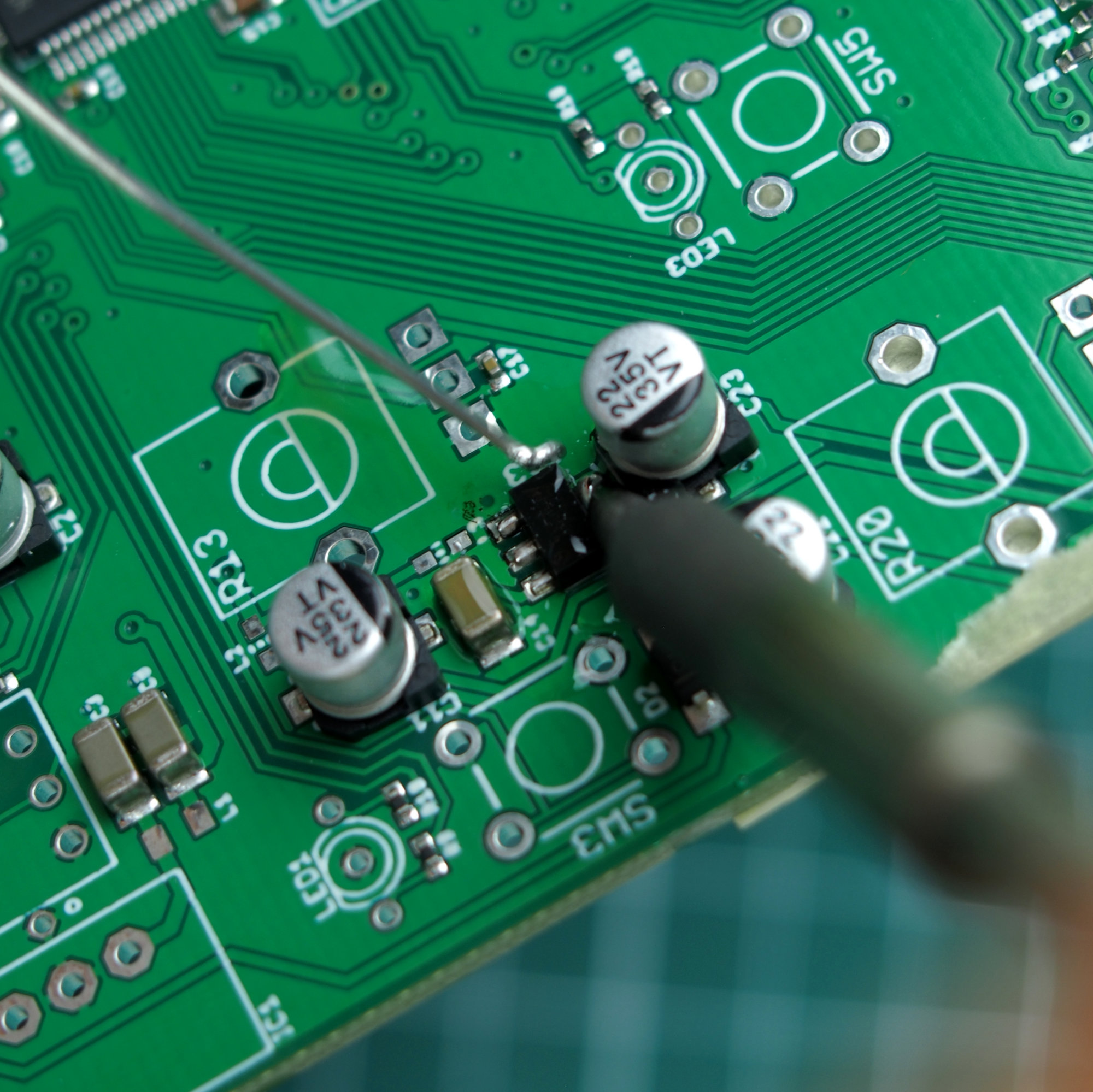
Follow a similar procedure for this one. First align it, then fix one pin in place and solder the remaining ones.
The big "heatsink" pin can be quite tricky to solder, because theres an electrolytic capacitor right next to it. You should be able to get your soldering iron into the gap though, touching the capacitor briefly by accident shouldn't lead to any issues, just be careful to not completely melt the plastic it sits on.
Soldering the Resistors, Ceradiodes, Inductors and Ferrites
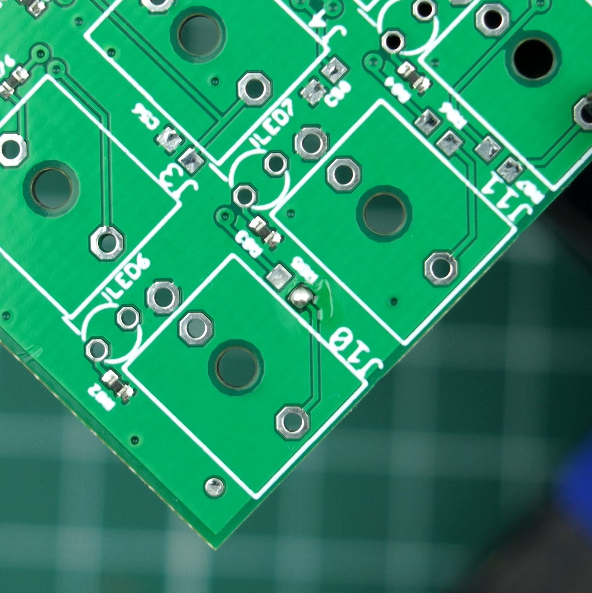
Next are the 0603 output protection resistors and ceradiodes. (The ceradiodes aren't super critical, they are only for additional input ESD protection and could potentially be omitted.)
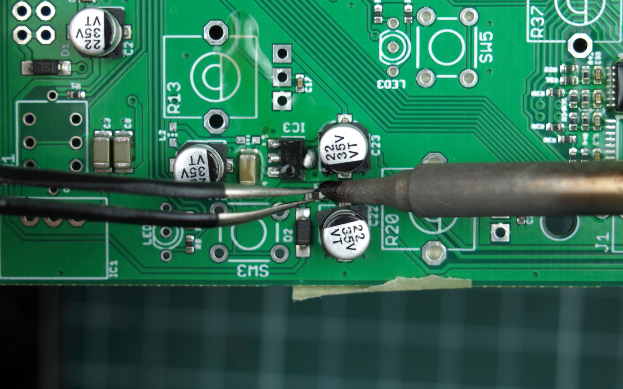
My prefered way of soldering 0603 components is applying a little bit of solder to one of the pads, grabbing the part with a pair of tweezers, reheating the solder and dropping the part in. After that, you can solder the other pad.
Same goes for the Inductors and Ferrites. Some of these are a little finicky, because they are once again close to several big electrolytic capacitors. Like before, try to find an angle to fit your soldering iron, without touching the neighboring components too much.
# Firmware & Calibration
Soldering the required THT Components
Before soldering any front panel components, you should flash the module and test for basic functionality. In case you have a soldering error, fixing it after all the big potentiometers, jacks etc. are soldered can be very hard.
To flash the firmware though, you first need to solder 3 more through hole components, which are the DC-DC converter, SWD header and power connector (IC1, JP1, JP4). These are very straight forward to solder, just make sure they are well aligned and sit flush against the board.
Setting up the Programming Environment
For firmware programming, start by setting up the mutable dev environment according to the instructions from the README. Make sure you can successfully build the firmware via:
$ make -f marbles/makefile hex
To test the analog inputs and the dac, aswell as calibrating it, I've made some changes to the
original testing routine in marbles.cc, added some template code for calibration to
settings.cc and also added a python script, which helps automating the process.
You can download the patch containing said
changes or alternatively a zip,
containing only the edited files (if you have problems applying the patch).
To apply the patch, simply navigate to the eurorack-modules directory and apply it via
git apply:
$ cd /vagrant/eurorack-modules/
$ curl "https://30350n.de/static/downloads/marbles_calibration.patch" -o marbles_calibration.patch
... # or manually download the patch and move it into the folder
$ git apply --ignore-whitespace marbles_calibration.patch
... # ignore any warnings that might come up
To quickly test that the patch worked, navigate to the marbles directory, make the script
executable and run it.
$ cd marbles/
$ chmod +x calibrate.py # might not be necessary
$ ./calibrate.py
flashing test firmware ... error # expected, if no programmer is connected
Powering Up the Module
Note: Before powering up the module for the first time, it's generally considered good practice to check for shorts on the power rails. Checking for shorts between the +12V, GND and -12V rails can be done directly via the power connector. For analog 3.3V, check for shorts between the outer pins of any potentiometer.
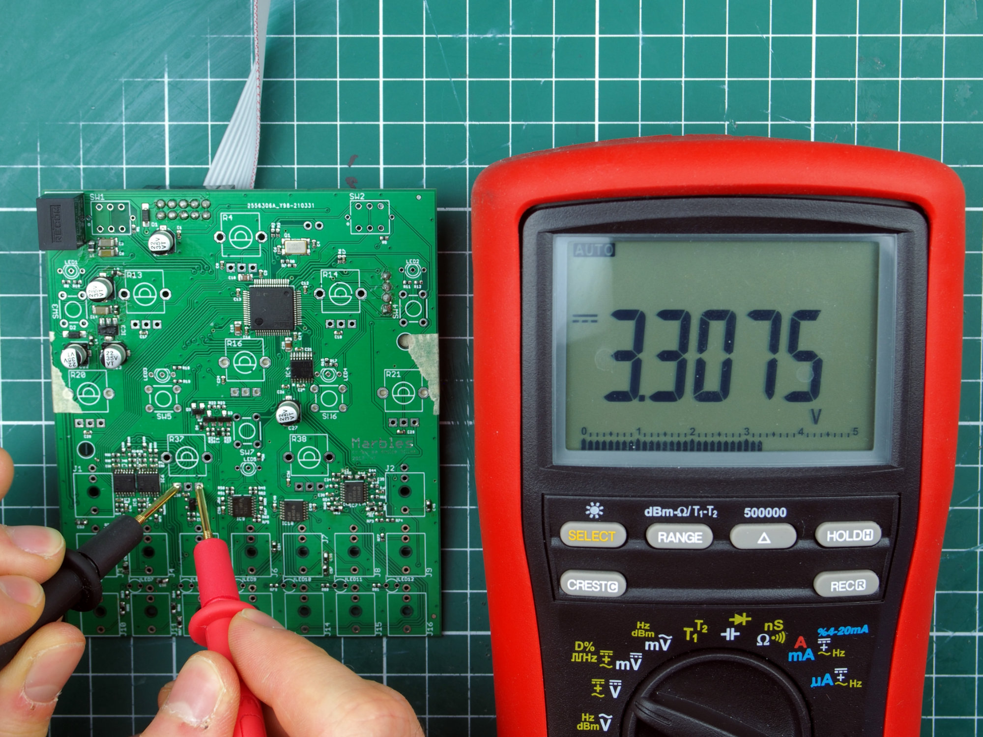
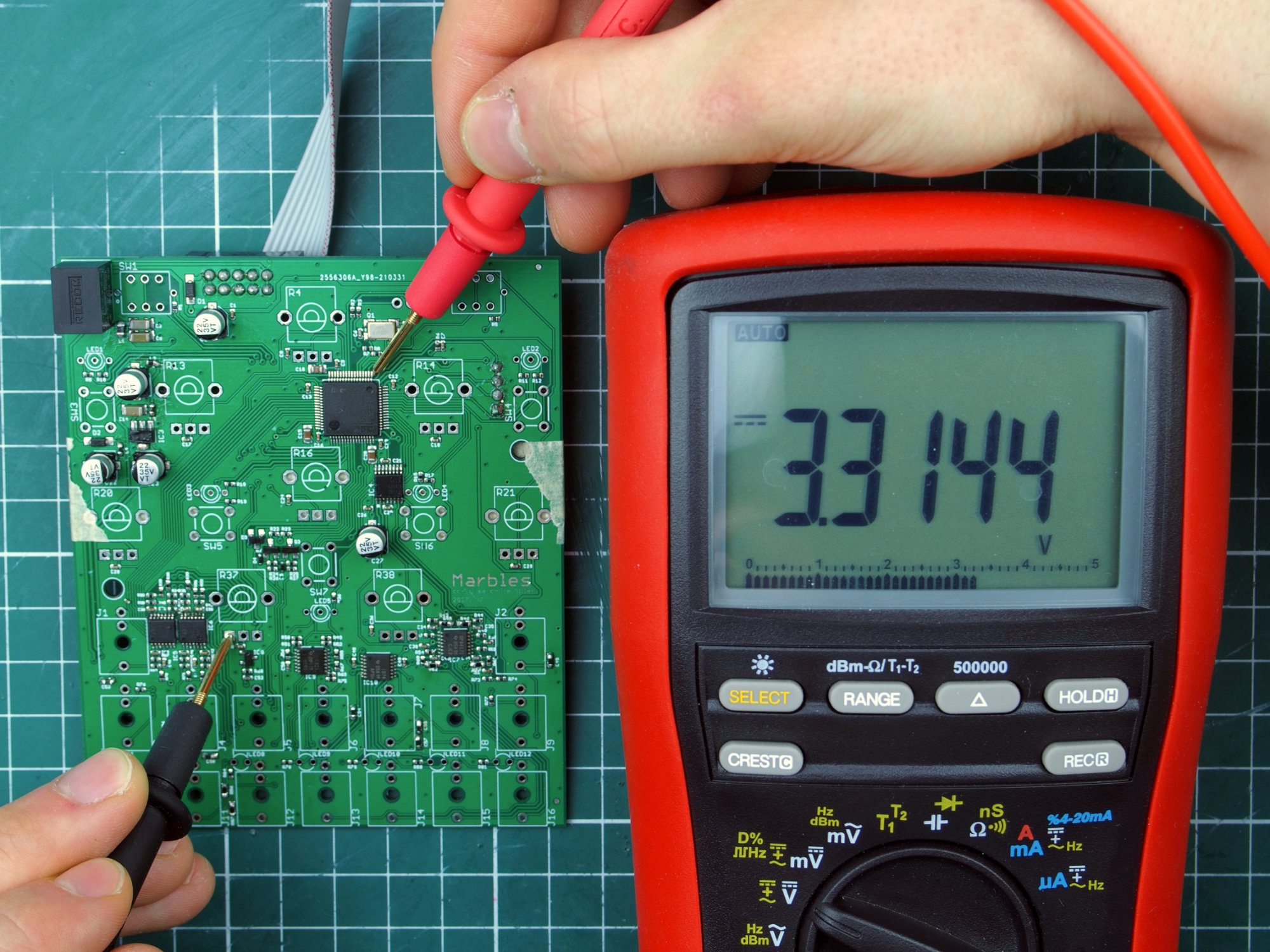
Connect the module to power and check if both the analog and digital 3.3V rails are working.
For analog 3.3V you can do that by measuring the voltage between the outer pins of any
potentiometer and for digital 3.3V the leftmost pin of any potentiometer and the rightmost pin
of the top row of pins of the STM32F405 (IC2).
If any of those aren't present, immediately disconnect the power, check if anything's hot or
if you missed any shorts on the power rails.
Connecting the Programmer
Next, connect your programmer to the SWD header, its pinout is: RESET, SWCLK, SWDIO, GND (top to bottom) and to your computer. Startup the mutable-dev-environment. The programmer should be automatically available in the VM.
To manually build and flash the firmware, navigate to the eurorack-modules directory and run:
$ make -f marbles/makefile upload
To automate the build and calibration process though, you can also use the aforementioned python script I created. Run it and wait until it flashed the test firmware. While doing so bend out the middle leg of a 3 pin R/G LED and insert it into the LED1 or LED2 footprint. The bent leg should create enough tension for the LED to stay in place and to ensure electrical contact to the board.
Testing the Analog Inputs
The LED acts as way to give feedback about the status of the analog inputs. It enables you to
easily test whether or not each analog input is working.
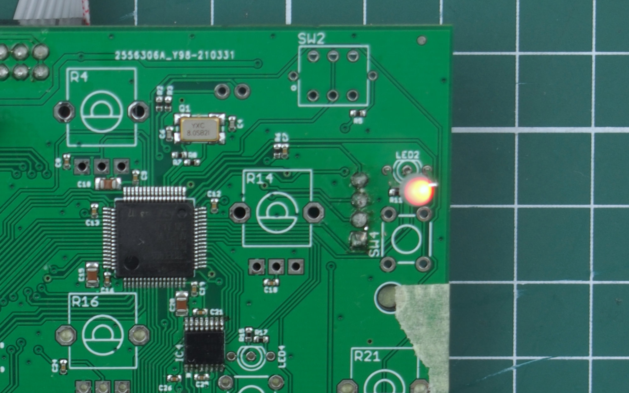
After the test firmware is flashed the LED should not light up. If it does, that most likely
means that you didn't properly solder one or more pins of the MCP6004s. The LED should only
light up, if a voltage of > ~1V is present at one of the 7 analog inputs. The color with which
the LED lights up, depends on which input the voltage is present at. If you input a voltage of
~1V on each input, left to right, the color should switch between
red and
green
in alternating fashion.
Calibrating the Outputs
After confirming that all the inputs are working, it's time to test and calibrate the outputs. You can measure the voltage at each output jack (J13 - J16) by measuring between their top (GND) and bottom pins accordingly. The voltage at each output should switch between ~0.9V and ~2.9V every few seconds. If any of them don't behave like that, that most likely means that you didn't properly solder the DAC8164 (IC4).
The script should now prompt for the 1V output at J13. Wait until the output at J13 switches to ~0.9V, measure the exact value and enter it into the prompt. Repeat for the 3V (~2.9V) output and for all other outputs. When you are done, the script will calculate the required scale and offset for each dac channel and reupload the now calibrated test firmware.
The output voltage of each output, should now measure more or less exactly 1V or 3V
accordingly. Next, the script will ask whether or not you want to repeat the calibration
process. If you aren't happy with it, you can repeat it by answering with y. Otherwise reply
with n and proceed. Finally, the script will ask whether or not you want to save the
calibration data. Either enter a valid filename or leave it blank to skip saving. After that,
the actual marbles firmware will be flashed.
If everything works out, the LED you inserted earlier should now light up. Disconnect the
programmer aswell as the powersupply and proceed with soldering the front panel components.
Example calibration process:
$ cd marbles/
$ ./calibrate.py
flashing test firmware ... done
check cv inputs, gate outputs, calibrate cv outputs:
J13 1V: 0.9236
J13 3V: 2.9276
J14 1V: 9450 # the 0. can be omitted
J14 3V: 9553 # same for the 2.
J15 1V: 9753
J15 3V: 9636
J16 1V: 9126
J16 3V: 9185
flashing test firmware (calibrated) ... done
repeat? (y) n
save calibration? my_calibration
flashing firmware (calibrated) ... done
# THT Assembly
Soldering the Buttons
Start by inserting the 5 tactile buttons (SW3 - SW7). They should just snap into place with a little bit of pressure. For each button, solder two opposite legs into place and check if the buttons still sit flush against the pcb. If everything looks good, solder the remaining legs to the board. At this point, you can also already put the caps onto the buttons.
The two illuminated push buttons (SW1, SW2) are a little more tricky. Orientation is critical here. There is a little dot/circle on the silkscreen of the pcb, next to the switch footprint. This has to align with the colored/white dot on the push button. After figuring out the orientation, proceed soldering them in the same way as the other buttons. Once again, make sure they sit flush to the board.
Soldering the LEDs, Potentiometers and Jacks
Put in all the LEDs, potentiometers and jacks, but don't solder them yet.
For the LEDs, once again, orientation is critical. The 3-pin LEDs have a little notch on one side which you should be able to see/feel. This should align with the silkscreen graphics. For the 2-pin LEDs, there are two little lines above the pads. One of them (the left one) is longer than the other one. This indicates that the longer leg of the LED should go into that hole.
After putting all the components into their place, put on the panel and tighten all the potentiometers and jacks to it, carefully. Then turn everything around, make sure all the LEDs fall into their holes and if everything looks correct, start soldering everything down.
If everything works out, add knobs to the potentiometers and you're done!